
Instrumentation and Data Acquisition
ME 331 & 332 - Instrumentation and Data Acquisition and Lab - in this Mechanical Engineering course, I studied the fundamental concepts of engineering instrumentation. Topics include the study of fundamental DC circuits and the theory of operation and selection criteria for various temperature, pressure, flow rate, displacement, speed, force, strain, torque, time, and power measurement devices. Computer data acquisition techniques are stressed, with hands-on applications in the laboratory.
In the lab, we analyzed different methods of acquiring data, and also examined which method works best for a given situation. For example, in one lab we examined different tachometers. A tachometer is any device that measures the rate of revolutions of an object. We used a circular disk with a circumference of one foot and we were able to set the RPM of the disk anywhere from 0-4000 RPM.
The best measuring device for this situation is the optical encoder, a device that sends a laser beam though holes in a spinning wheel. At the other side of the wheel there is a sensor that can determine how many times the laser's light is hitting the sensor, and from this it computes the rotational speed.
Another device that did not work so well is either the handheld electronic tachometer or the handheld mechanical tachometer. These two devices measure the RPM using the same method, except one has a digital readout, while the other one has a meter. This device measures the rotational speed by inserting a probe into the center of the wheel. This probe then turns and the rotational speed is displayed on the digital panel or the meter.
The reason why the optical encoder is preferred over the handheld tachometer is because the optical encoder is non-intrusive. This means that the device takes the measurements without affecting the speed of the wheel. In many situations it is important to have a non-intrusive device. The handheld tachometers are highly intrusive, and they cause the wheel to slow by 25% in this case. This puts an extra load on the motor and also does not measure the correct RPM because once the device is no longer connected, the RPM of the wheel increases.
One of the most interesting topics we studied in lab were load cells. A load cell serves two basic purposes: it measures the amount of strain on a member and the amount of force on it. This is important information to know in order to find out if a member is close to failing and what the factor of safety is.
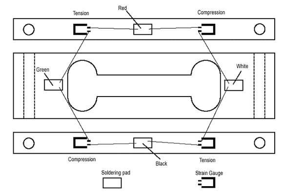
In our lab, we designed a binocular load cell (see image below) to have a strain close to 1500 micro strain when a force of 40 pounds is applied. We then programmed a CNC machine to automatically cut the load cell out of a block of aluminum. Once we had the actual load cell, we then connected it to a strain box and computed the calibration curve. We tested the load cell by applying a 40 pound force and the strain measured was what we had calculated so our design was a success.
We used this load cell to perform another test after we concluded that it could calculate the proper force to measure the force and strain of a four pound pendulum. We connected the strain box to a data acquisition board and set up a program to calculate the the strain and force subjected on the load cell for 10 seconds in increments of 0.02 seconds. For additional information and a more detailed description of the experiment please read the report.
Click here to view my resport.
