
Manufacturing and Design
ME 210 - Manufacturing and Design - this mechanical engineering class is very similar to the ES 101 class I took freshman year because of the design aspect. In this class I worked on two main projects. For the first project, students were given the design of a gearbox and we were instructed how to build it piece by piece. The purpose of this was to introduce students to all of the design software, which includes AutoCAD, Mechanical Desktop, and the Virtual Gibs program, and also to all of the equipment in the machine shop, which includes a CNC machine, lathe, drill press, and a Bridgeport. In the second project, students worked in teams of four to design and build a min-dragster for competition.
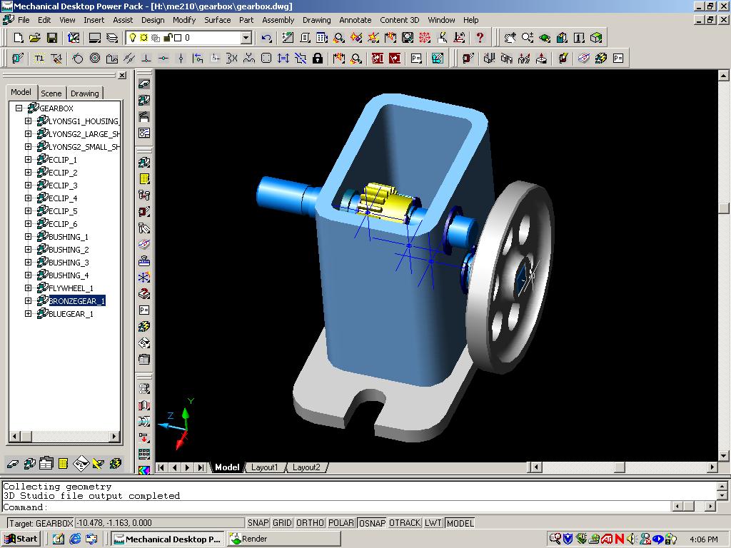
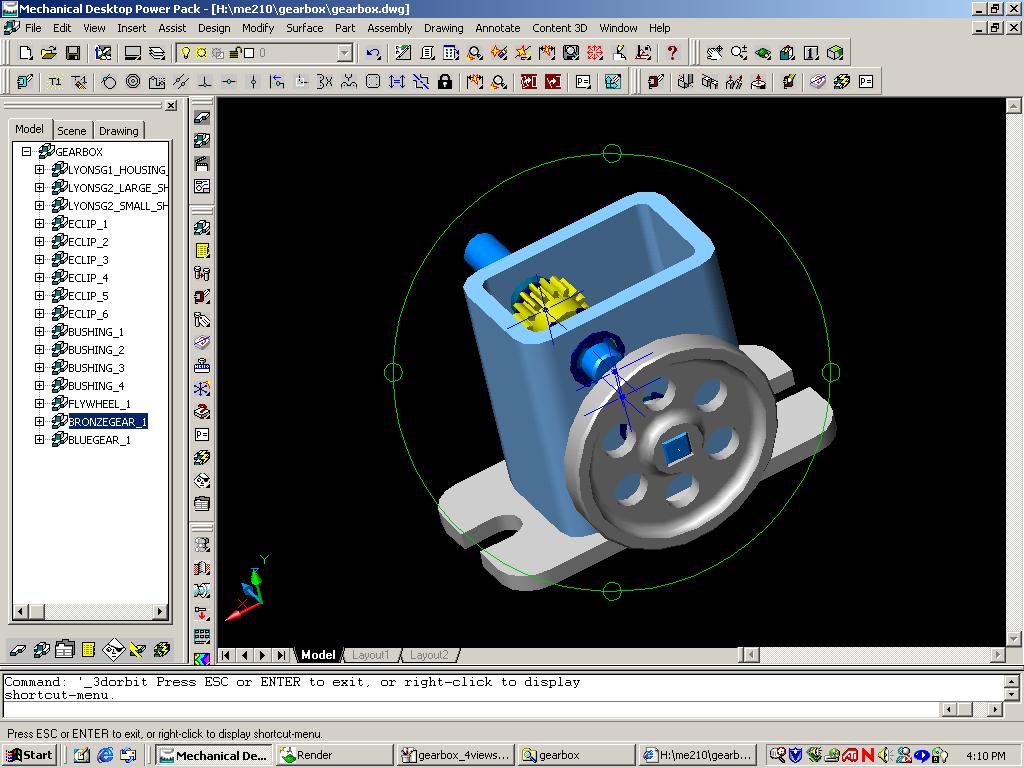
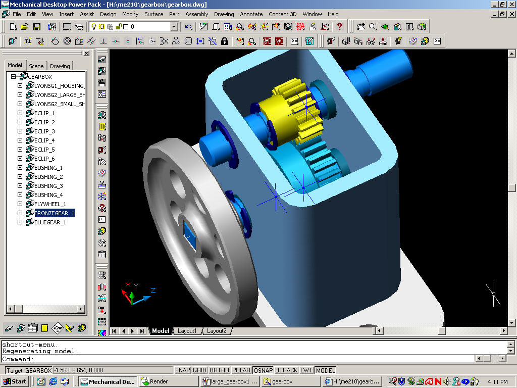
To start the first project, students were taught how to use Mechanical Desktop by drawing all of the parts for the gearbox. This included a base, housing, two gear shafts, six e-clips, four push bearings, and a flywheel. Our professor provided drawings of the two gears for us. After we had all of the parts drawn, we then began to assemble the gearbox in 3D. This process was mainly to help verify all the dimensions are correct and to see that all of the parts fit properly.
Once all of the drawings were in order, we then printed off a dimensioned drawing of each part, which we used while in the machine shop. This step was easy to accomplish because Mechanical Desktop allows you to prepare drawings from several different views such as top, front, and bottom with any dimension you want on it. It also creates an isometric drawing if needed.
Using the dimensioned drawings we created ourselves, we used the various machines to make each of the pieces for the gearbox. For flywheel, we used the CNC machine, which we programmed with the Virtual Gibs program.
Here are some link to images of the final design that we drew in Mechanical Desktop. The gearbox made a nice souvenir to keep.
 |
 |
 |
 |
I also created a short video animation of the gearbox. Click here to load the video.
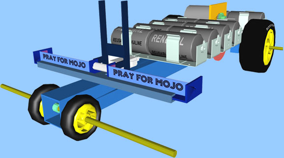
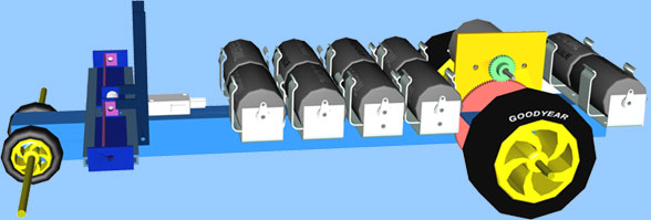
The second project was very challenging, but also a great learning experience. The goal of the dragster was pretty simple. It must drive straight on a 26-foot track as fast as possible and stop within three feet. At the finish line there is a bar five inches above the track that can be used to initiate a breaking system. If the dragster goes beyond three feet, then a time penalty will be assessed. To make this project oriented to engineers, we also had to make the car as cost effective as possible. Everything we used to build our dragster involved some kind of cost, even the time in the machine shop.
In the end, our car came in second out of ten overall. We had produced the most cost effective car, and the only one that was able to break 100% of the time. Our best time was 2.76 seconds for the 26 feet.
Here are a few images of the car drawn in Mechanical Desktop